Reading Ground Reports for Slurry Microtunnelling
From borehole logs to machine selection and site control
By Oğuzhan Ataşalar
Before a microtunnel drive starts, I want one question answered clearly: Do we understand the ground well enough to prepare the right machine and site setup?
A report may contain hundreds of pages. What matters to me is whether it helps us make practical decisions. What will the machine pass through? Where could we lose slurry? Where could tools wear faster? Can the separation plant handle the material? What happens if we have to stop?
Machine capacity, a good operator and reliable maintenance all matter. But they need to be supported by a realistic understanding of the ground. This is how I approach borehole logs and geophysical reports on slurry microtunnelling projects.
1. Start with the tunnel position
Before looking at test results, I check where the tunnel sits in the ground profile.
A description such as “dense sand” or “limestone” is not enough. I need to know whether that material covers the full face, only the bottom of the cutterhead, or the ground above the pipe.
My first checks are simple:
- Are the borehole levels and design levels based on the same datum?
- Is the diameter shown the pipe inside diameter, outside diameter or excavation diameter?
- Is the cover measured to the tunnel centre or the top of the excavation?
- Are the water levels shown clearly?
I want the boreholes, shafts, utilities, groundwater and rock level on the same long section. I also want the top and bottom of the excavation shown, not just the centreline.
The ground between two boreholes is interpreted. A straight line on the drawing does not prove that the layer continues evenly between them.
2. Check whether the investigation answers the right questions
More boreholes do not automatically mean better information. Their location, depth and sample quality matter just as much.
I look more closely at shaft areas, soil–rock transitions, old fill, possible boulders and water-bearing zones. If the available information does not explain an important risk, we need further investigation.
I do not apply the same borehole spacing or depth to every project. The investigation needs to suit the tunnel, the shafts and the ground conditions.
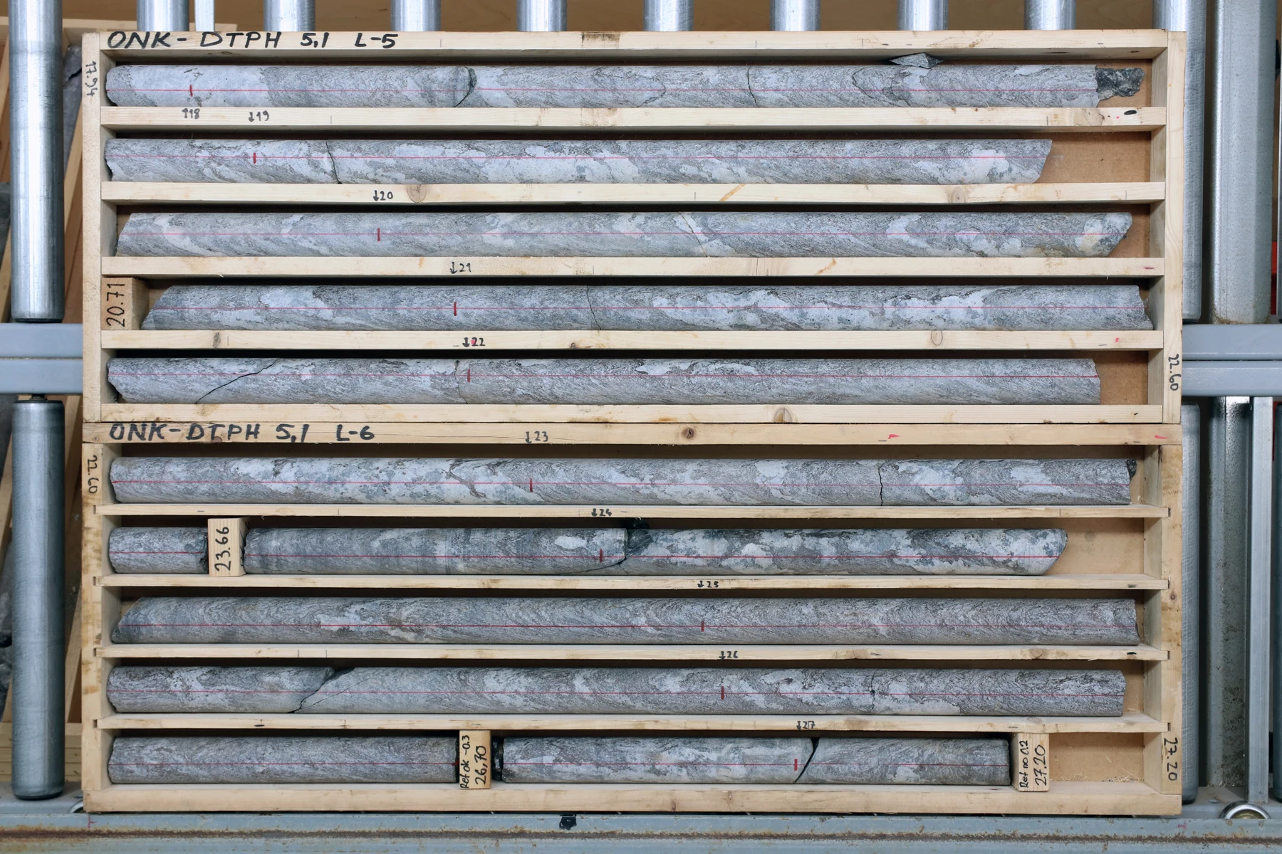
The drilling notes also deserve attention. Core loss, water loss, hole collapse and sudden refusal may tell us something important. But they need interpretation. Water loss may suggest permeable ground or open fractures; it does not identify the exact cause on its own.
A small borehole can miss a large boulder. It can also miss old concrete, timber or other buried obstructions. Where that risk matters, I want a suitable follow-up investigation rather than an assumption that the route is clear.
3. Do not make the whole decision from an SPT value
SPT results are useful, but one N value cannot tell us everything about machine performance.
First, I check whether the report gives the raw N value or a corrected value. I then read it together with the soil description, test details and laboratory results.
Dense sand can still need careful face support below the water table. A high blow count in gravel may come from the sampler hitting a large particle. Refusal may mean rock, a boulder, a cemented layer or old concrete.
In clay, I also need water content, plasticity and suitable strength information. I do not use SPT to predict abrasivity or decide whether clay will stick to the cutterhead.
What interests me most is a change along the route. If the results change suddenly, I want to understand why before the machine reaches that area.
4. In rock, strength is only part of the picture
When I read a rock log, I check rock type, weathering, core recovery, RQD, fractures, strength and abrasivity together.
UCS tells us the compressive strength of an intact rock sample. It does not tell us everything about the rock mass, cutting performance or tool life. I want to see the range of results and where the samples came from, not just an average.
RQD helps describe the condition of the recovered rock core. High RQD does not automatically mean easy excavation. Strong, massive rock can require high cutting loads. Low RQD can bring loose blocks, uneven loading and water-bearing fractures.
Abrasivity needs separate attention. Strong rock is not always highly abrasive, and weaker material can still cause serious wear. Suitable tests and mineral information help us assess that risk, but no single result gives a guaranteed tool life.
For a long drive, the important question is whether the tools can complete the distance, and what access we have if they cannot.
5. Give mixed face its own assessment
A face with rock in one part and soil in another needs special attention.
The cutterhead meets different cutting resistance across the same face. This can affect tool loading, wear, steering and ground loss in the softer material.
I want the likely transition areas identified before launch. I also want the team to understand how uncertain those locations are.
I do not assume the machine will always move in one direction at a mixed face. Ground geometry, machine balance, cutting behaviour and steering all affect the result.
Where possible, a change in alignment may reduce the risk. But it must also work with the required gradient, existing utilities, shaft depths and project limits.
6. Understand the groundwater pressure
“Groundwater is four metres below ground” is only the starting point.
I check when the level was measured, which layer it represents and whether nearby dewatering affected the reading. Separate water-bearing layers may have different pressures.
Under hydrostatic conditions, ten metres of fresh-water head gives approximately one bar of pressure. The head is measured from the relevant water level to the point being assessed. It is not simply the depth of the tunnel below ground.
Water pressure is also not the same as the required face support pressure. The face needs enough support to remain stable, while excessive pressure can cause slurry escape, ground movement or hydraulic fracture.
I therefore want a calculated operating range for the project. I do not set face pressure from a fixed number of bar per metre of cover. I also keep pump discharge pressure separate from excavation chamber pressure.
Launch and reception need their own assessment. Headwalls, seals, ground treatment and dewatering must work together. One does not automatically replace another.
7. Keep slurry and pipe lubrication clear
The excavation slurry supports the face and carries the excavated material to the separation plant.
The lubricant injected around the pipes reduces contact and friction between the pipe string and the ground.
Both may use bentonite, but their purpose, mix and pressure requirements are different.
For the excavation circuit, I look at particle sizes, permeability, clay behaviour, water chemistry, pumps and pipeline capacity. More bentonite is not always the answer to slurry loss. The mix must suit the ground and the equipment.
Clay can create another problem: sticking to the cutterhead or building up in the system. Plasticity matters, but so do water content, mineralogy, flushing and cutterhead design. Adding water or chemicals without checking the effect can create further problems.
For pipe lubrication, I track injection locations, pressure, volume and the response in jacking loads. A high recorded bentonite volume does not prove that lubrication is effective around the pipes.
8. Choose the separation plant for the material
I do not select a separation plant from its m³/h rating alone.
Hydraulic capacity and solids-handling capacity are different. A plant may handle the flow but struggle to remove the fine material. As fines build up, slurry properties change and production can suffer.
I assess the expected excavation rate, particle-size distribution, solids load and waste handling together. Fine-rich ground may need additional treatment or dewatering equipment, depending on the required slurry quality and disposal arrangements.
Water supply, tank space, tankers and disposal capacity also need to match the production plan. These are part of the tunnelling operation. If they fall behind, the machine can lose working time even when it is mechanically ready to advance.
9. Use geophysics to support the ground model
Geophysics can help us understand the ground between boreholes. But a coloured section is an interpretation, not a photograph underground.
Different methods answer different questions. Seismic methods provide information about wave velocities and ground stiffness. Resistivity surveys respond to changes that may involve water, salinity, clay or rock type. Ground-penetrating radar can help with shallow targets in suitable conditions, but conductive clay and saline water can limit its depth.
Before accepting a conclusion, I ask:
- What was the survey trying to find?
- Did it investigate down to tunnel level?
- Could it detect a target of the size we are concerned about?
- Was the interpretation checked against boreholes or other site information?
- Where is the result uncertain?
“No anomaly detected” does not mean “no obstruction”. We first need to know what the method could detect under those conditions.
10. Select the machine for the full drive
“Can this machine excavate this material?” is not enough.
I also ask whether it can finish the full drive with the expected wear, groundwater pressure, slurry conditions and jacking loads.
Cutterhead selection needs to consider rock strength, abrasivity, boulders, clay, mixed face and material flow. Crusher capacity, torque, cutter loads and drive capacity need to be checked with the manufacturer.
Access for tool inspection and replacement must be clear before launch. Many small machines offer very limited access during a drive. Some larger or specially designed machines allow internal tool changes, subject to the machine arrangement and safe intervention conditions.
A rescue shaft is not an easy answer to every problem. Traffic, depth, utilities, groundwater and permits may make it difficult or impractical.
11. Manage jacking loads before they reach the limit
The capacity of the main jacks is not the same as the allowable load on the pipes.
I check the pipe manufacturer's limits together with joint angles, load transfer, alignment and project conditions. The reaction structure and intermediate jacking stations also need to be included.
Friction changes with lubrication, ground conditions, curvature, deviation and stoppages. Restart loads deserve particular attention.
I do not decide the number of intermediate jacking stations from drive length alone. The calculation must consider the expected loads and difficult operating conditions.
On site, I want action levels agreed in advance. We should know when to review lubrication, use an IJS or stop for assessment before the load reaches the allowable limit.
12. Keep using the report during the drive
Once tunnelling starts, the ground report should remain part of daily control.
Before launch, I want a short table showing the expected ground and main risks by chainage. The operator and site team should know what changes are expected and what to watch for.
During the drive, I read torque, advance, face pressure, jacking loads, flows, slurry properties and steering together. A rise in torque alone does not prove that we have entered rock. It could also mean clogging, tool wear or a mechanical problem.
Feed and return flows need careful interpretation. Their difference is not a direct measurement of excavated ground. Density, tank levels, fluid losses, additives and measurement errors all affect the balance.
Material reaching the separation plant is useful feedback, but it arrives after a delay. It needs to be matched to the correct excavation chainage.
When the machine behaves differently from the ground model, I want the reason investigated. Increasing thrust or pressure is not a solution to every problem.
Clear records also matter. Machine data, samples, photos and stoppage details help us understand the actual ground and assess any difference from the contractual baseline. A difference does not automatically mean an entitlement to extra time or payment; that depends on the contract and the evidence.
What I expect from a good ground report
A useful ground report should help us choose the machine, prepare the cutterhead, plan slurry treatment and understand where the drive needs closer control.
We cannot remove every uncertainty. We can identify the gaps, investigate the important ones and prepare for the risks that remain.
Before the machine starts, I want the team to understand both the expected ground and the plan for working through it.
Further reading
Pipe Jacking Association — An Introduction to Pipe Jacking and Microtunnelling
U.S. Geological Survey — Borehole Geophysics
This article explains my general approach to reviewing ground information. Project-specific design and operating limits must be established for each drive.